Model: 50608
Brand: AEGIR
Place of Origin: China
Catalogue
1. Hardware Description …………………………………………………………1
1.1 Device Description ………………………………………………………..… 1
1.2 Device Installation ……………………………………………………….…2
1.3 Device Operations ……………………………………………………….…2
2. System Description ………………………………………………………..…3
2.1 Software Feature ………………………………………………………….…3
2.2 Hardware Feature ……………………………………………………………3
2.3 System Requirements ………………………………………………………3
2.4 Software Installation ………………………………………………….…… 4
2.5 Software Management Instructions ………………………………….4
2.6 Server Connection Settings ………………………………………………5
2.7 Function Module Select ……………………………………………………6
3. 3.1 Terminal Management …………………………………………………7
3.1.1 Terminal Settings ……………………………………………………..… 7
3.1.1.1 Terminal added ……………………………………………………..…7
3.1.1.2 Deleting a Terminal ……………………………………………………8
3.1.1.3 Viewing Terminal Status ……………………………………………9
3.1.1.4 Function Settings of Terminals ……………………………………9
3.2 Data Management …………………………………………………………11
3.2.1 Data Query
………………………………………………………………..11
1. Hardware description
1.1 Device Description:
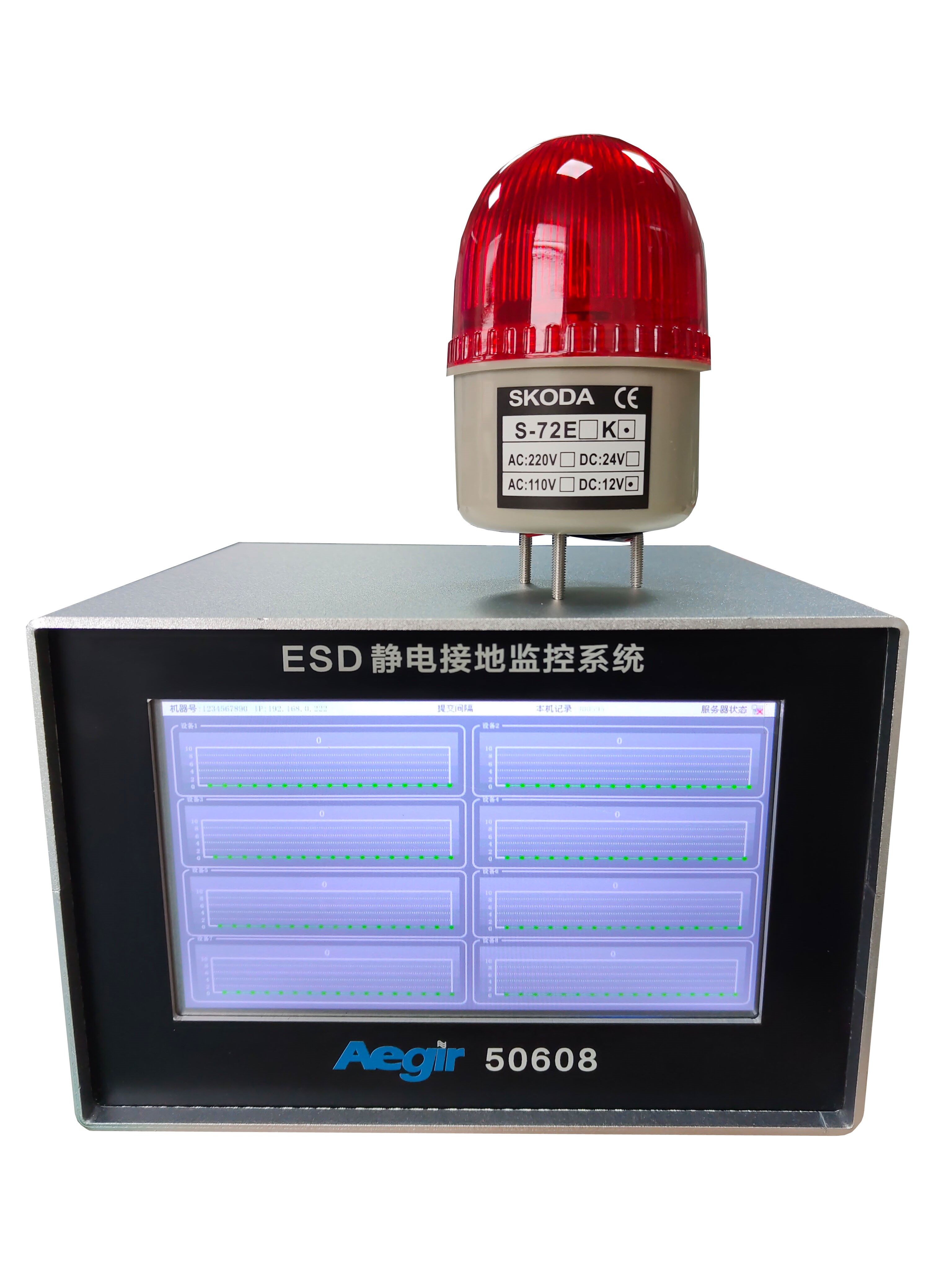
AEGIR50608 intelligent electrostatic grounding resistance monitor, used to monitor whether various equipment grounding, electrostatic grounding wire, production line grounding and electrostatic pile grounding wire is well grounded, or whether the grounding resistance is qualified, whether it meets the electrostatic protection standard, and record the data in real time and upload it to the server. The data can be filtered according to the date at will, and the report can be generated, which is convenient for the customer's audit and production department management. AEGIR50608 is a precision test instrument, which needs to be corrected regularly (once a year).
50608 Kit:
• ESD ESD grounding monitor host
• Alarm light + stand
• Alarm light power 12VDC power adapter (100-240VAC input power)
• 5VDC universal power adapter (100-240VAC input power)
• Ground cable
• Operating instructions
Product features:
• Support network communication, can upload 60,000 records in less than 15S
• Online upgrade via the network (cross-domain upgrade possible)
• All parameters are set on a PC and can be controlled remotely
• Built-in perpetual calendar accurate timing, can be automatically timed through the network
• Can store 10 million records, and power failure data is not lost
• Abundant I/O ports for controlling other external devices
• Used by large enterprises, mass data test,
stable and reliable performance
Basic specifications of ESD static grounding monitor host:
|
Protocol standard: |
ISO15693、ISO14443A |
|
Operating frequency: |
13.56MHz |
|
Communication interface: |
RJ45(TCP/IP) |
|
External power supply: |
DC12V/3A |
|
Power consumption: |
<2W |
|
Display screen: |
LED liquid crystal display screen |
ESD static grounding monitor Physical parameters:
|
Overall dimensions: |
215*295*60mm |
|
Machine weight: |
2kg |
|
Housing material: |
304 the whole machine does not embroider steel |
|
Protection level: |
IP53 |
ESD static grounding monitor environmental parameters:
|
Working temperature: |
-20℃~+70℃ |
|
Storage temperature: |
-30℃~+80℃ |
|
Storage humidity: |
5%~95% No condensation |
ESD electrostatic grounding monitor measurement standards:
|
ESD electrostatic grounding monitor: |
Lower limit (0 ohms, error + -1%) |
|
ESD electrostatic grounding monitor: |
Upper limit (1-200 ohms) can be set according to actual requirements |
1.2 Device Installation:
1) When using 50608, fix the host of the electrostatic tester on the wall or other suitable positions
2) Ground the host of the electrostatic tester with a matching ground cable
3) Connect the remaining ground wires to the main terminal of the monitor (connecting holes 1-8).
4) Use the matching power adapter to insert the power jack of the host of the electrostatic tester
5) Connect the alarm to the host as required.
Attention! Before switching on the power supply, the host of the ESD static grounding monitor must be reliably grounded before it can be turned on.
Attention! ESD If the monitor is not grounded, the
internal chip may be damaged.
1.3 Device Operations:

1: monitoring cable port
2: alarm light wiring
3: Power jack
4: indicates a network cable socket
5: Reset switch (restart button)
6: indicates the standby debugging port
2. System description
2.1 Software Features
■ Through TCP network connection, all network access control products are managed by the same software;
■Friendly interface, smooth operation;
■Can display and automatically collect access control data in real time, and other functions can be customized according to needs (such as sound and light alarm, etc.); Support SQL Server database;
■Provides data import and export function, convenient processing; (Automatic import and export requires running background services);
2.2 Hardware Features
■ 7 "touch screen;
■ When the server cannot be connected, the instrument can store 10 million data records locally, with a large capacity. Users can set the local data batch upload time, stable speed, easy to operate;
■ Instrument time is automatically networked and synchronized to avoid time deviation;
■ Can be networked and single machine operation;
■ Low power consumption;
2.3 System Requirements
To install and use the access control software, the following operating conditions are recommended.
Operating system: Windows 10 or later. Non-windows systems are not supported. (If you need to run LINUX and other systems need to be customized)
Database: MS SQL Server 2008 or later
CPU: I3 or higher
Memory: 8GB or above
For a large system, for example, if the number of controllers exceeds 50, the system performance must be increased as the number of controllers increases. You are advised to increase CPU performance and memory capacity first.
2.4 Software Installation
For the minimum requirements for installing access control software, see the previous system requirements.
Access control software installation steps:
1. Install the MS SQL Server database. SQL2008 is recommended.
2. Install the control software. Just follow the wizard prompts to complete the installation.
3. Attach the provided database file to the SQL2008 database.
4. On the control software, set the server IP address, port number, database account, and password.
5. After the software is installed and the database runs normally, double-click the software icon to start the software.
6. The default startup user name and password are 001. You can change the user and password after the login. 001 The account cannot be deleted.

2.5 Software Management Overview
Basic management process
1 Install the software.
2 Run and log in to the software.
3 Set parameters.
4 Query data.
2.6 Server Connection Settings
Double-click twice in the blank area of the login and
input password interface to appear the setting button

Click Settings to enter the
server Settings screen

This section describes how to
set server information
2.7 Function Module Selection

Select the middle icon
3. Device grounding monitoring and management system
3.1 Terminal Management
3.1.1 Terminal Settings

Set up your device in this
screen!
3.1.1.1 Terminal Addition
Click on the red


Then enter the terminal SN
number, SN enter 10 digits!
Name Fill in the name you want!
Layer not selected!
IP Enter the IP address of the device!
The submission interval is selected according to the
actual situation!
3.1.1.2 Deleting a Terminal

Click Delete!
3.1.1.3 Viewing Terminal Status

Double-click the terminal you
want to view

The latest data will then be displayed on this screen, with the dial
gray indicating not enabled!
3.1.1.4 Function Settings of Terminals

The button in the red box can set whether the device is enabled or not!

You can enter the device name in the red box!

Select the resistance limit in the red box!

Click OK when the Settings are complete!
Note that the Settings will take a while to take effect, a delay of about 10
seconds!
3.2 Data Management

3.2.1 Data Query

Select Eight way equipment in the red box!